SVC-03 / 08Solid and surface models
3D CAD Modelling
Parametric models and full digital assemblies
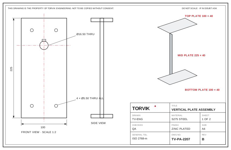
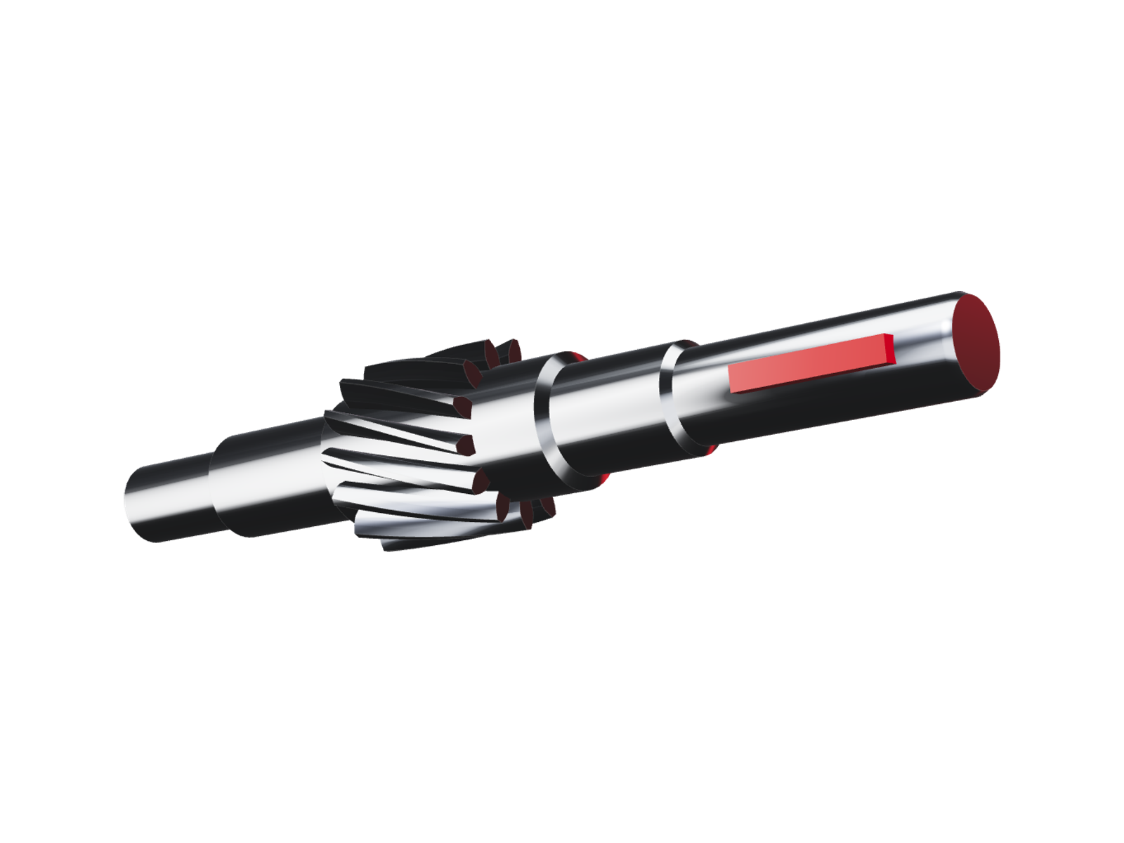
Accurate models in SolidWorks, CATIA and Creo, built on clean parametric feature trees: change a dimension and the model follows, with nothing to redraw.
Why it works here
Models your team can keep using
Every sketch is fully constrained and every reference holds. Your engineers can open the tree, follow it and build the next variant themselves.
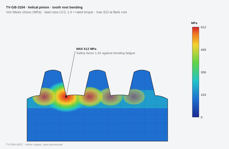
Our engineers sit next to our own CNC machines, gear cutters and assembly benches, so every analysis is checked against what the works can actually make.
Where it is applied
Sectors
- A
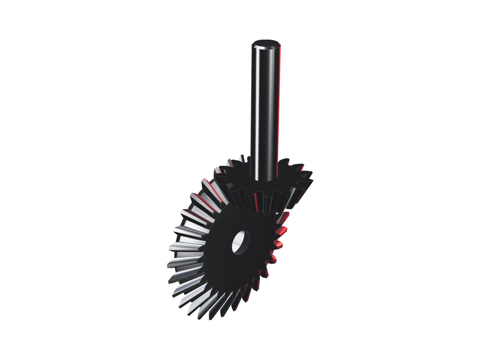
Precision gearboxes
Gear trains over several stages, with housings and bearing fits.
- B
Castings & forgings
Draft, parting lines and shrink allowance modelled to the foundry's rules.
- C
Fabrications & sheet metal
Flat patterns and bend tables ready for laser cutting and forming.
What you receive
| Item | Deliverable |
|---|---|
| 01 | Parametric solid models |
| 02 | Freeform and complex surfaces |
| 03 | Sheet metal and cast part models |
| 04 | Digital assemblies with clearance and interference checks |
| 05 | Files in native format, STEP and IGES |
Tools & standards
- CAD
- SolidWorks, CATIA, Creo
- Model
- Parametric solid and surface
- Exchange
- Native, STEP, IGES
- New parts
- First article report, AS9102 format
- Design practice
- ASME / ISO DFM
- Every batch
- EN 10204 · type 3.1
Where it sits in a programme
3D CAD Modelling works at the Design stage of the five that every programme runs through, from concept to manufacture.
- P-01ConceptFeasibility, system architecture, ideation
- P-02This serviceDesign3D parametric CAD, DFM reviews, detailing
- P-03AnalysisFEA structural, CFD fluid flow, thermal
- P-04PrototypeRapid 3D print, CNC first-offs, validation
- P-05ManufacturePrecision machining, GD&T, volume supply